What is a Control Valve and How Does It Effect My Control Loop?
WHAT IS A CONTROL VALVE AND HOW DOES IT AFFECT MY CONTROL LOOP?
Control valves may be the most important, but sometimes the most neglected, part of a control loop. The reason is usually the instrument engineer’s unfamiliar- ity with the many facets, terminologies, and areas of engineering disciplines such as fluid mechanics, metallurgy, noise control, and piping and vessel design that can be involved depending on the severity of service conditions.
Any control loop usually consists of a sensor of the process condition, a trans- mitter, and a controller that compares the “process variable” received the transmitter with the “set point,” i.e., the desired process condition. The controller, in turn, sends a corrective signal to the “final control element,” the last part of the loop and the “muscle” of the process control system. While the “sensors” of the process variables are the eyes, the “controller” the brain, then the “final control element” is the hands of the control loop. This makes it the most important, alas sometimes the least understood, part of an automatic control system. This comes about, in part, due to our strong attachment to electronic systems and computers causing some neglect in the proper understanding and proper use of the all important hardware.
Control valves are the most common type of final control elements; however, there are other types such as:
- Devices that regulate (throttle) electric energy such as silicon- controlled rectifiers,
- Variable speed drives,
- Feeders, pumps, and belt drives,
- Dampers
Some of these devices perform functions similar to control valves and could be used as an alternative. For example, in order to control the pH level, a variable stroke-type metering pump may be used to inject acid into wastewater (instead of using a control valve lined with polytetrafluorethylene [PTFE])
What then is a control valve? This is a difficult question since there is consid- erable overlap with other types of valves. For example, a valve operating strictly in the on-off mode (such as the hydronic solenoid valve in your home heating sys- tem) could be replaced by a simple ball valve operated by a pneumatic cylinder, a type usually referred to as an “automated valve.”
The distinction between “automated” and “control” valves is usually consid- ered to be the ability of the latter to “modulate,” i.e., to assume an infinite number of “throttling” travel positions during normal control service.
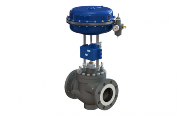
Physically, there are three basic components of a control valve:
- The valve body subassembly. This is the working part and, in itself, a pressure vessel.
- The actuator. This is the device that positions the throttling ele- ment inside the valve body.
- Accessories. These are positioners, I/P transducers, limit switches, handwheels, air sets, position sensors, solenoid valves, and travel stops.
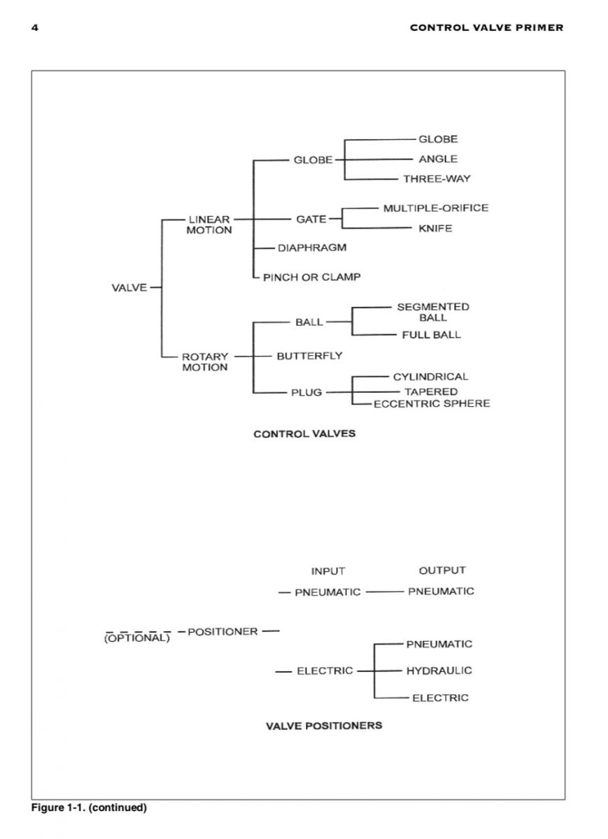
A more detailed breakdown of the various types of valves, actuators, and positioners is shown in Figure 1-1.
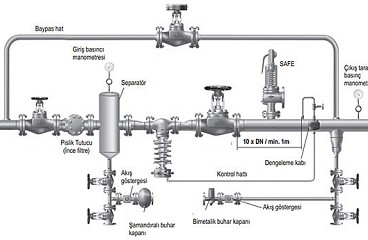
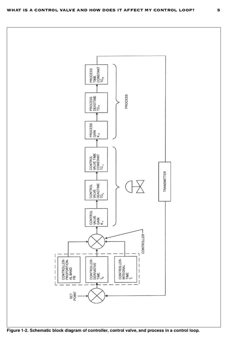
Now let’s discuss what the control valve should do. Referring to Figure 1-2, which shows a somewhat simplified process control loop diagram, we see three important function blocks above the control valve symbol.
The first one is control valve gain, Kv. This is determined by the “installed flow characteristic” of the valve (quite different the characteristic shown in the vendor’s catalog). Kv tells you how much the flow through the valve is chang- ing per a given signal change. For input see Chapter 8.
The second block shows the control valve dead time, TDv. This is the time it takes before a valve moves following a controller signal change. This is usually determined by the valve and actuator friction but may include time lags due to long pneumatic signal transmission lines and the time to build the pressure up in a diaphragm case, for example.
Finally, the third block shows the time constant of the valve, TCv. This is sim- ply related to the stroking speed of the actuator or actuator/positioner combination (see Chapter 9), i.e., how fast the valve is responding to an upset in your controlled variable. All these function blocks interact, and each one should be considered in evaluating a control valve application.
The “ideal” valve should have a constant gain throughout the flow range, i.e., a linear “installed” flow characteristic, no dead time with packing tightened, and a time constant that is different that of the process by at least a factor of three.
Need I tell you that there is no such thing as the “ideal” control valve? So let’s attempt to develop a workable compromise.
WHAT TO LOOK FOR IN A GOOD CONTROL VALVE DESIGN
Besides the obvious, such as good quality workmanship, correct ion of mate- rials, noise emission, etc., special attention should be paid to two areas:
- Low dead band of the actuator/valve combination (with tight packing).
- Tight shutoff, in cases of single-seated globe valves and some rotary valves (if required).
The prime concern of an operator of a process control loop is to have a loop that is stable. (Nothing makes people more nervous than a lot of red ink and scat- tered lines on a strip of paper a recorder.) The final control element will influence the stability of a loop more than all the other control elements com- bined.
The biggest culprit here is “dead time.”l This is the time it takes for the con- troller to vary the output signal sufficiently to make the actuator and the valve move to a new position. What we are talking about here is that the dead time, TDv, is the time it takes for the pneumatic actuator to change the pressure in order to move to a different travel position. It is most commonly related to the “dead band”1 of the actuator/valve combination, or, in case a positioner is used, the dead band of the valve divided by the “open loop gain”2 of the positioner plus the positioner's dead band (dead band keeps the valve responding instantly when the signal changes, which, in turn, causes dead time). The valve itself should never have a dead band of more than 5% of span, that is, less than 0.6 psi for a 3 to 15 psi signal span or 0.8 mA for a 4-20 mA signal. The positioner/valve combination should have no more than 0.5% of signal span. Ignoring process dynamics, a positioner may, therefore, improve matters by an order of magnitude. However, positioners can raise havoc with the dynamics of a control loop (see Chapter 9). The ideal valve is still the one in which the operating dead band with tight stem packing is less than 1%. There you have maximum stability without the extra cost and complication of having to use a valve positioner. Unfortunately, the majority of valves can not operate without a positioner. Luckily, modern position- ers have electronic tuning capabilities that can help to drive the dead band down (see Chapter 9).
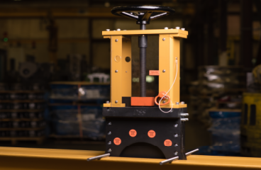
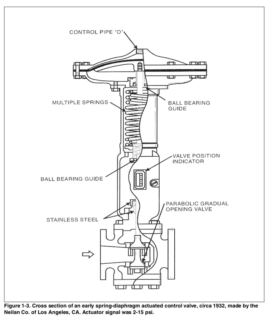
The very first control valves recognized the value of low dead band. The valve in Figure 1-3, for example, features ball-bearings around the actuator stem in order to avoid twisting the spring and thereby reducing friction (circa 1932). Low seat leakage can be very beneficial. First, it saves you the extra expense of a shut- off valve in case the system closes down. (Note: For safety reasons, never rely on the control valve for absolute tight shutoff.) Second, it saves energy. Third, it is an unqualified requirement in temperature control applications in a batch process,
1 This is often confused with “hysteresis,” a dead band produced by moving the actuator up and down through 100% travel. Hysteresis is not very important in a “closed-loop” system.
2 Usually 50 to 200. Consult vendor’s published positioner catalog.
Especially when you are supplying a heating fluid to a chemical that can undergo an exothermic reaction.
Another feature is good rangeability. As you probably already know, valves are usually terribly oversized. That is, they operate only at perhaps 30% of their rated Cv under normal flow conditions. Furthermore, it is not wise to operate a conventional valve trim at less than 5% travel.1 The reason is that the controller might be slightly unstable at the low flow rates, and the actuator, following the sinusoidal output of the controller signal, will push the plug against the seat. When this happens, the actuator and positioner will bleed all the air out, and you end up having a really big dead time, (before the valve gets moving again) upon signal reversal. In short, you have a big mess and no control.
Using the 5% travel limit, we find that the Cv is only about 7% of the rated Cv with a linear characteristic and not much less with most equal percentage charac- terized plugs. This gives us a useful range for the above-normal Cv of 30% divided by 7%, which is 4.5:1. However, in most loops the pressure drop across the valve always varies inversely with the flow, that is, a low DP at maximum flow and a high DP with low flow. We, therefore, might find that the actual controllable ratio of maximum to minimum flow is perhaps only 3:1. Incidentally,
this ratio is the so-called “installed” rangeability, which, as you can see, is quite different the “inherent” rangeability shown in a manufacturer's catalog for the same valve. A simple way to remember is that the “inherent” valve rangeability is the ratio of maximum to minimum controllable Cv, while the “installed” rangeability is the ratio of maximum to minimum controllable flow rate in your loop.
REFERENCES
1. McMillan G. K., and Weiner S., How To Become an Instrument Engineer - The Making of A Prima Donna. Research Triangle Park, NC: ISA (1987).
1- Without a positioner and with high packing friction, such as graphite packing, the minimum travel position should be higher than the dead band caused by the packing friction (usually 7% to 10%)!